
 Español




There are no more items in your cart

GMDSS MODULE PROS 12-24V SECURE COMMUNICATION. EMERGENCY BATTERY
€577.17
Tax included
Ensure safe and reliable communication while navigating with the GMDSS MODULE PROS 12-24V.
Ensure safe and reliable communication while navigating with the GMDSS MODULE PROS 12-24V. This emergency battery module is designed to automatically switch your VHF and GPS systems to a backup power source, ensuring compliance with GMDSS regulations for both recreational and professional maritime activities.
- Automatic Switching: Seamlessly transitions to emergency power during battery failures.
- Regulatory Compliance: Meets GMDSS standards for fishing, passenger, rescue, and work vessels.
- Reliable Communication: Maintains essential communication channels in emergencies.
- Versatile Power Supply: Compatible with 12-24V systems for diverse marine applications.
Invest in your maritime safety today with the GMDSS MODULE PROS for peace of mind on the water.
Technical Specifications:
When connecting the module in AUTOMATIC mode, it analyzes the state of the batteries and if it is correct, it emits 3 beeps, turns on the status LEDs, and provides power to the radio from the service battery.
When the module detects that the service battery is below 24V or 12V, depending on the position of the selection switch, it switches the radio to the emergency battery, the service status LED blinks, and the buzzer is activated.
When the module detects that the emergency battery is below 25.0V (or 12.5V), it makes the emergency status LED blink, activates the buzzer, and if used, the charge relay.
The buzzer can be disabled using the "STOP" button, but if the battery status does not change, it will reactivate after 59 minutes.
If the service battery recovers and exceeds the switching voltage by 0.5V, the module will switch the radio back to the service battery.
Using the front selector, we can force it to work directly on emergency or on service; in the latter case, the module will be disconnected.
PROSXBE INSTALLATION INSTRUCTIONS
Connect the shunt of the emergency battery charge/discharge ammeter to the negative terminal of the battery.
Connect the two measurement wires of the shunt to the ammeter using the orange two-way connector, respecting the polarity indicated in the diagram.
If the emergency battery is charged with an automatic charger, use the diagram without the charge relay.
If the emergency battery must be charged from the same alternator as the service battery, use the diagram with the charge relay, which will disconnect the charging current approximately 1 minute after reaching 28.8V for 24V batteries and 14.4V for 12V batteries.
The service battery and the emergency battery must be of the same voltage, 12V or 24V, and the dip-switch marked in the corresponding position must be set before powering the module.
Connect the four wires to the gray connector of the module according to the indications in the diagram.
The maximum output current to power the radio and GPS is 12A and is protected by a resettable thermal fuse.
Secure the module to the panel with screws 3.5 x 16 (11248616) or to the joining pieces.
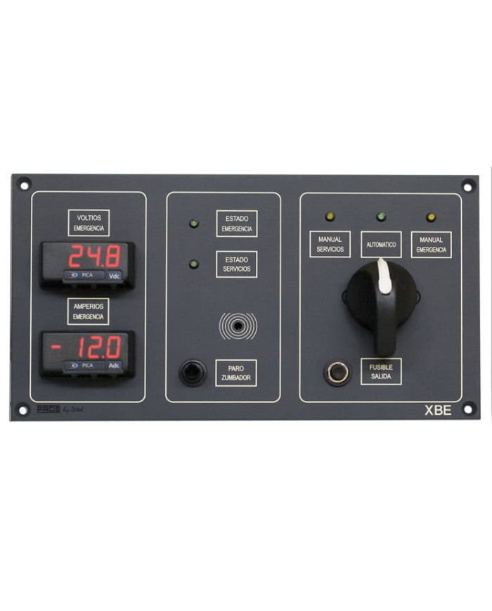
This PROSXBE module includes:
• 1 Screen-printed board 240 x 130 mm.
• 4 Screws 3.5 x 16
• 2 Green LEDs battery status
• 1 Green LED automatic mode
• 2 Yellow LEDs manual batteries
• 1 Manual/automatic selector
• 1 Emergency battery voltmeter
• 1 Emergency battery ammeter
• 1 Stop button for buzzer
• 1 Resettable output fuse
• 1 Instruction manual